Imagine trying to land a helicopter on a hotel building in the depth of the night, in the middle of a city during foggy weather. How can you land safely without seeing where you are going? Air traffic controllers are an example of radar-assisted systems which help pilots to land no matter the weather and lighting condition. Radars were originally developed during World War II to detect enemy aircraft, but nowadays you can see their footprints everywhere from autonomous cars to smart-home robots. In this article, I will elaborate on a specific type of radars called mmWave radars which are extremely beneficial for fine-grained tasks like localization, tracking, gesture recognition and so on.
Back in the day, it took around eight hours for the first versions of cameras to take a picture – and it was still blurry! Nowadays, thanks to the high-quality lenses, we can take amazing high-quality pictures for our Instagram in less than a few milliseconds. But how does a lens work? Light not only bounces off of objects but also passes through them which can alter its direction. A camera lens focuses all the light rays bouncing around to a single point, creating a sharp image.
We have almost the same logic for RADARs (RAdio Detecting And Ranging), except for the fact that they are working on a different frequency range and they are usually active. Radars transmit electromagnetic waves then, they perform a set of processing pipelines on the reflected waves to provide us with information about the surrounding environment. Moreover, radars can be monostatic or bistatic. In monostatic radars the sender and the receiver are co-located, while in bistatic radars the sender and the receiver are in separate locations. In the picture below, the principle of a monostatic radar is shown.
mmWave Radars
Radars have a broad range of applications including air and sea traffic control, moving target indication (MTI), missile and remotely piloted vehicle guidance systems, weather prediction, tracking, speed guns, and automotive and vehicular applications. Each application has a different set of requirements which can be realized in a specific frequency range. Here we have the well-known radar equation:
![R_{max}=\sqrt[3]{\frac{P_sG^2\lambda^2\sigma}{P_{E_{min}}(4\pi)^3}}](https://ksp-windmill-itn.eu/wp-content/ql-cache/quicklatex.com-442624f90a82453676d394ed7fd655ea_l3.png "Rendered by QuickLaTeX.com")
Where  and
and  are the maximum detectable range, transmitted power, antenna gain, wavelength, radar cross-section, and minimum detectable received power respectively. If the operating frequency is high enough (the wavelength is considerably less than the range and the size of the target) so that the radar cross-section is independent from the frequency, the higher the frequency, the lower the detection range. mmWave radars, as their name suggests, work on the mmWave range as shown in the following figure.
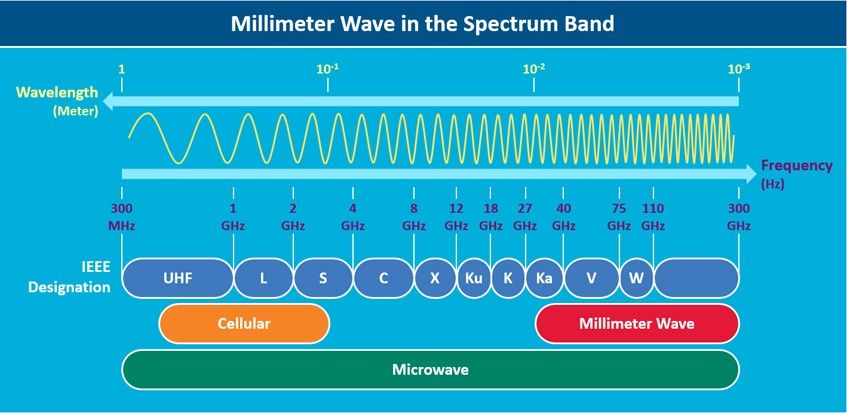
Using lower wavelengths enables mmWave radars to provide sub-mm range accuracy and penetrate certain materials such as plastic, drywall, clothing. Moreover they are robust to environmental conditions such as rain, fog, dust and snow as well as lighting conditions.
FMCW (Frequency-Modulated Continuous Wave)
As the name implies, FMCW radars transmit a frequency-modulated signal continuously to measure range, angle and velocity of targets. While the traditional pulsed-radar systems transmit short pulses periodically. In the following sections we will see the working principles of the FMCW radars.
Range Measurement
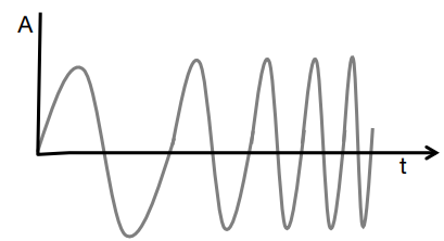
As we mentioned before, the fundamental concept in radars systems is the transmission of an electromagnetic signal and receiving the reflected signal from the targets. In FMCW radars, a signal with an increasing frequency through time called chirp, is used for this purpose. The following figures shows schematic representations of a chirp in time and frequency domains.
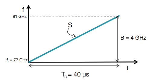
A chirp is characterized by its start frequency ( ), bandwidth (
 ), duration (
 ). Additionally, the slope of the chirp (
 ) represents the change rate of the frequency. Having received the reflection, a frequency mixer create a new signal based on the transmitted and the received signals.


Where  is the transmitted signal and
  is the reflected one.
  is the output of the mixer:

Since the received chirp is a time-delayed version of the transmitted chirp, the frequency of (intermediate frequency) is constant. Furthermore, the time delay ( ) can be derived as:

Where  is the distance of the target from the radar and
  is the speed of light. In summary, for an object at distance the IF signal will be the following sine wave:

Where  and
and  . So far, we discussed the range measurement for a single object. But what will happen in case there are multiple objects? We will receive multiple reflections with different delays depending on their distance from the radar. The different reflected chirps translate to multiple IF tones, each with a constant frequency which should be processed using Fast Fourier transform to separate the different tones.
Range Resolution
The ability of a radar to distinguish between multiple targets called range resolution. According the Fast Fourier theory, the higher the length of the IF signal, the better range resolution. Consequently, the bandwidth must be increased proportionally. Two IF signal tones can be separated in frequency as long as:

Where is the observation interval. As a bottom line, the range resolution ( ) depends only on the bandwidth:

Long story short, an FMCW radar with a chirp bandwidth of a few GHz will have a range resolution in the order of centimetres. Now, we can see that in mmWave range, although the penetration power decreases, due to the availability of wider bandwidths, the range resolution can be very precise. The velocity and the Angle of Arrival (AoL) is also measured by this kind of radars which is described in https://www.ti.com/lit/wp/spyy005a/spyy005a.pdf.
Pantomime: mmWave radar based mid-air gesture recognition
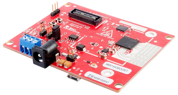
In the second part of this post, I want to focus on our latest paper published in IMWUT 2021 entitled Pantomime (Point cloud-based Activity recognition NeTwOrk using MIlliMEter wave radar): Mid-Air Gesture Recognition with Sparse Millimeter-Wave Radar Point Clouds. In this work we designed a system based on an IWR1443 radar for recognizing mid-air human gestures from sparse point clouds.
Why mmWave radar?
We utilized the mmWave radar to position Pantomime in a unique region of the RF technology landscape as a miniaturized medium-resolution medium-range high-frequency RF sensing approach, providing privacy-awareness and robustness to occlusion, weather conditions, and visibility issues.
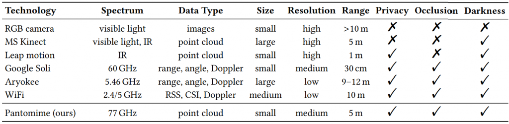
As shown in the above figure, Pantomime has various advantages over RGB cameras including privacy-awareness and occlusion to weather and lighting conditions.
mmWave radar generated point clouds
Following a set of preprocessing pipelines described in Pantomime paper, a sparse point cloud is generated. A point cloud is a set of unordered points in a 3D space. The point clouds generated by the radar has not only spatial features, but also temporal features reflecting the evolution of gesture through time. In the following figure you can see an example of a point cloud recorded from a participant performing a gesture:

As shown in the above figure, the generated point cloud is noisy and highly-sparse (compared to that of other sensors like MS Kinect) which posses unique challenges in the processing phase.
Pantomime model
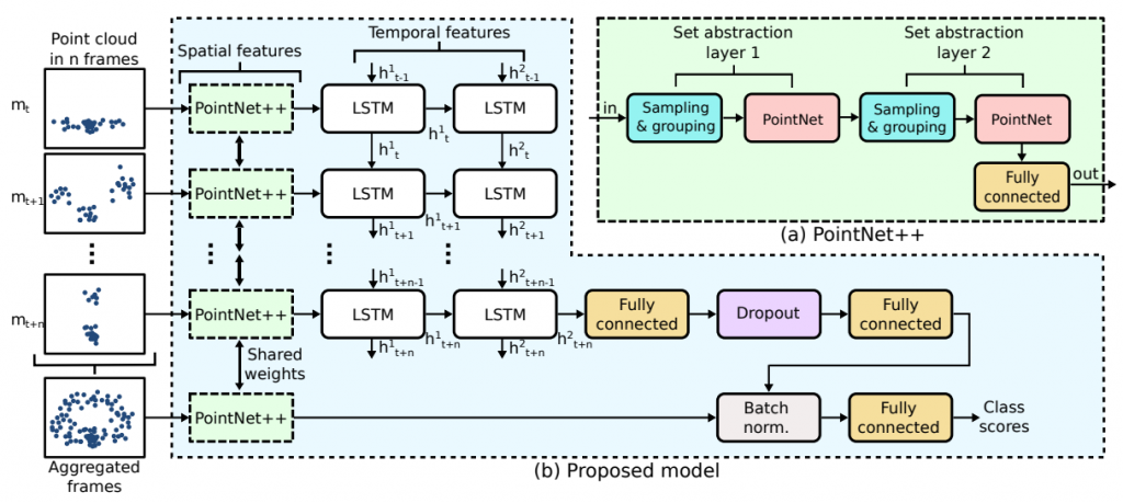
Using the unique features of the mmWave generated radar point clouds, we proposed a neural network architecture to recognize gestures. We extract the spatial features from each frame using a static point cloud encoder module, then fuse the spatial features through time to capture the temporal evolution of the gesture. In the following figure, the architecture of the proposed method is shown:
Results
To evaluate the model, we collected a dataset with the following features:
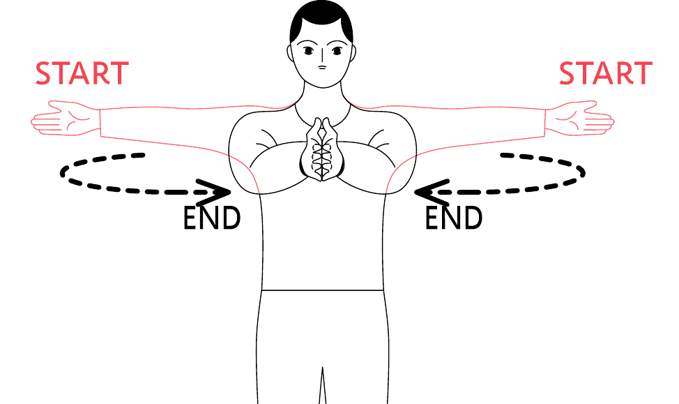
- 21 classes of gestures
- 5 environments
- 3 gesture performing space
- 7 angles
- different distances
- more than 40 participants
- more than 10,000 samples
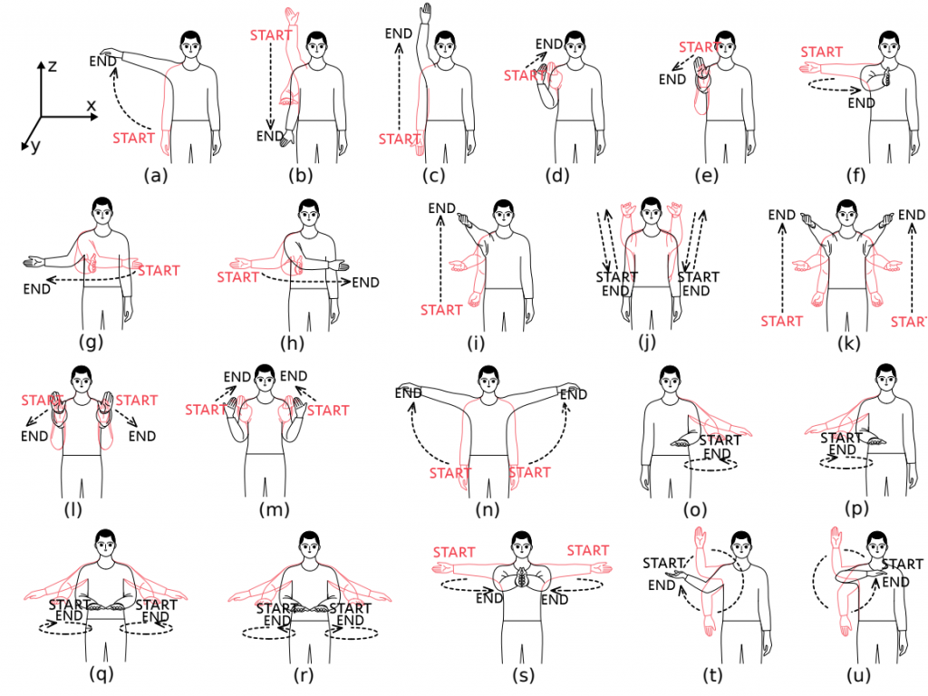
The complete set of gestures designed for the experiment is shown in the figure above. We published the dataset and the source code on Zenodo to let other researcher to reproduce the results and build upon our model.
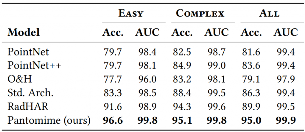
We have compared Pantomime to state of the art models in the above table. Pantomime outperformed all of them in three different settings of the dataset: EASY: a set of gestures that are easy to remember and perform, COMPLEX: a set of gestures that are mainly both handed or circular, ALL: all the 21 classes of gestures. You can see the rest of the results for different angles, speeds, distances, and environments in the paper.
What about sensing through walls?
Let’s come back to the title of the post “FMCW mmWave radars can see through walls!”. We collected data in a setting called “through-wall”. In this setting, we put the radar on one side of the wall and asked the participant to stay in the other side of the wall and perform the gesture. The setting is shown in the figure below.
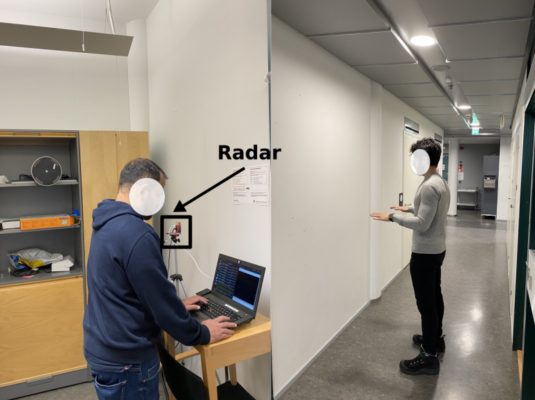
It is pretty obvious that in the same setting, if we use an RGB camera, the accuracy of the recognition will be 0% since the visible light cannot penetrate through walls. Whereas, using a mmWave radar we demonstrated that Pantomime can achieve an accuracy of 64.43%.
Conclusion
In summary, we discussed the basic principles of radars especially FMCW mmWave radars. Utilizing them, we presented our recent work entitled Pantomime, a novel mid-air gesture recognition system exploiting spatio-temporal properties of mmWave RF signals via 3D sparse point motion clouds.
Pantomime is positioned in a unique region of the RF landscape: mid-resolution mid-range high-frequency sensing making it ideal for mid-air gesture recognition. We also showed that we can sense gestures even through-walls which is one of the advantages of mmWave radars over RGB cameras.