The aim of this post is to describe the work “Assessing Wireless Sensing Potential with Large Intelligent Surface” published in IEEE Open Journal of the Communications Society. I will try to show the main ideas behind it in a more simplified manner. Please note that for a more detailed description of the methods and the algorithms we refer to the paper.
Large Intelligent Surface
A Large Intelligent Surface (LIS) could be defined as a continuous electromagnetic surface which is able to transmit and receive radio waves. It is also easily integrable into the environment (they can be placed on the walls/ceilings).
Although the majority of the research efforts have been focused on its communication capabilities, this post will be focusing on the future of 6G feature: its sensing capabilities.
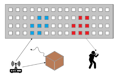
Fig. 1 shows an exemplary communication use case to get the better idea of the concept. An Access Point (AP) is trying to communicate with the user, but the direct path is blocked by an obstacle. Then, the radio signals travel towards the Large Intelligent Surface and the surface is “smart enough” to reconfigure its antenna elements and beamform the signal towards the user, thus solving the communication problem. We can see that it’s Large due to its huge aperture, Intelligent as a result of its reconfiguration capabilities and Surface thanks to its planar shape.
LIS-based Radio Sensing
In a wireless context LIS could be described as a structure which uses electromagnetic signals impinging in a determined scatterer in order to obtain a profile of the environment. We can use the resulting signal of the superposition of all the involved paths that imping into every element of the antenna conforming the surface. Then, the power of the resulting superimposed signal is used to obtain a high resolution image of the propagation environment. Note that the LIS elements are using the Channel State information (CSI) as envelope detectors, as no phase estimation is needed but the received signal power.
Using this approach the complexity of the multipath propagation is reduced to using information represented as an image. This provides a twofold benefit: i) the massive number of elements that compose the LIS lead to an accurate environment sensing (i.e. high resolution image), and ii) it allows the use of computer vision algorithms and Machine Learning (ML) techniques to deal with the resulting images.
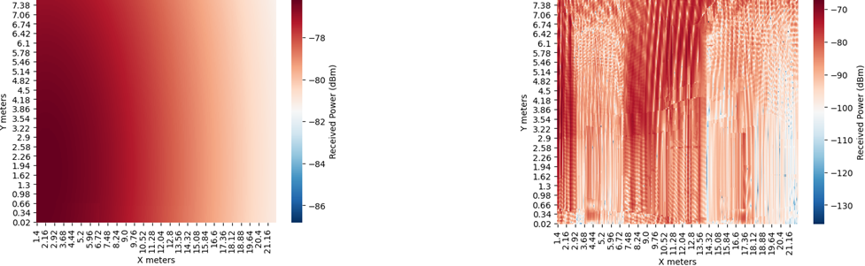
Fig. 2 shows two exemplary images. On the left hand side we have a simple Line-Of-Sight (LOS) case in which we can see the continuous image obtained at the surface. However, the interesting part is on the right hand side. In this case the LIS is deployed in a wall in an Industrial scenario. This shows how well the image describes the propagation environment, as it displays the shape of the objects/scatterers presented in the environment. In this way this information can be of interest to understand the radio propagation environment represented as an image.
Exemplary sensing use case: Industrial robot anomaly route detection using LIS
Let’s setup a simple baseline scenario in which we want to detect whether an industrial robot deviated from its predefined route or not.
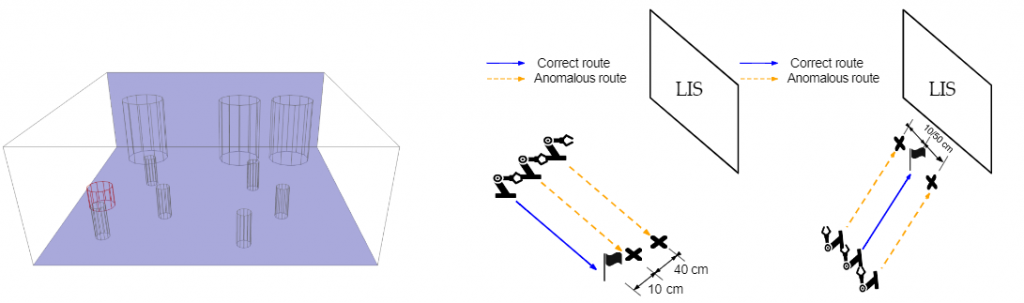
Fig. 3 shows the exemplary use case. The robot (highlighted in red color) is following its route while constantly transmitting a sensing signal. A LIS is placed on the bottom ceiling to obtain radio images that represent the environment with respect to the robot position. Different routes (parallel and normal) and different deviations (10/50 cm) are going to be leveraged to assess the precision of LIS sensing.
Methods to solve the problem
In the paper we presented two methods to solve the problem:
- We derive a statistical test based on the Generalized Likelihood Ratio (GLRT) as a benchmark for the machine learning solution.
- By treating a LIS as a radio image of the environment relying on the received signal power we develop techniques to sense the environment by leveraging the tools of image processing and machine learning. Once a radio image is obtained we use an unsupervised learning approach denoted as Local Outlier Factor (LOF). In addition, to improve the image quality, a Denoising Autoencoder (DAE) network can be used for constructing a super-resolution image leading to sensing advantages which are not available in traditional sensing systems.
The statistical test solution should be formulated under the assumption of noise statistics, as well as the prior knowledge of the probability of a transmission being done from a correct point in the route or a deviated one. This means that this statistical viewpoint solution will be of interest to benchmark the machine learning solution, in which no prior knowledge of probabilities or statistics is necessary to design the model.
The importance of noise averaging
The statistical solution presented has been derived by taking into account the presence of noise, and consequently it has implicit mechanisms to reduce its impact in the performance. However, the presence of noise may be more critical in the radio image sensing, since it considerably impacts the image classification performance. In this way, for every point in the route we obtain S extra samples. With these samples we average the received power signal, meaning that if we obtained enough samples the image will preserve the pattern with the only addition of an additive constant factor related to the noise power, removing the noise variance contribution which would degrade the pattern. This effect is only possible if the system is able to obtain a large number of S samples within each channel coherence interval.
Denoising Autoencoder for image super-resolution
In the field of computer vision autoencoders have been used for the idea of image super resolution. This means that the autoencoder is capable of learning how to improve the image from a lower quality to a higher one. Similarly, in the presented context, the radio images obtained at the LIS can take advantage of this method.
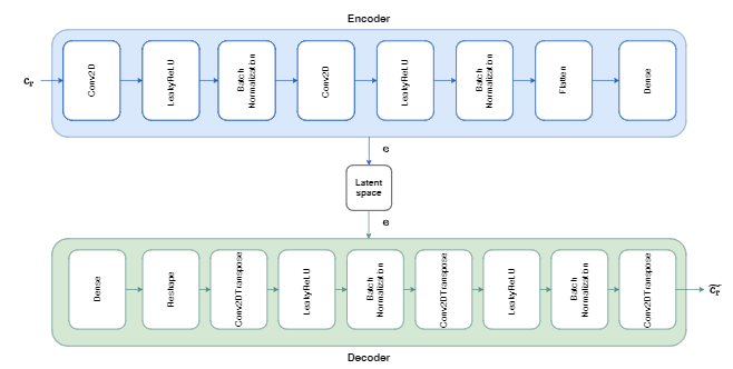
Fig. 4 shows the Autoencoder architecture used in the paper. The model is conformed of mainly two parts:
- Encoder: It will compress the input image to a lower dimensional structure called Latent Space, which preserves the spatial information of the input image data.
- Decoder: It will decompress the Latent Space resulting image in order to reconstruct the input image.
At first glance it seems that this autoencoder is just trying to learn how to compress and decompress the input image. However, if we train this autoencoder to learn how to reconstruct an input image as a higher resolution image we will improve the input image quality in the decoder output.
For that we will train the autoencoder, providing as an input images from the correct route of the robot with a smaller LIS at the ceiling (meaning we use less antennas under worse wireless conditions, i.e., higher noise, leading to obtaining a low quality image), having a higher resolution image as a target (better wireless conditions and higher number of antenna elements). In the results section we will see that this will lead to a significant improvement in the performance.
Numerical results and discussion
I will discuss some numerical results in order to analyse the performance of both proposals (statistical test and radio image sensing) in our evaluation setup described in the paper. Generally, in the considered industrial setup, it would be more desirable to avoid undetected anomalies (which may indicate an error in the robot or some external issue in the predefined trajectory) rather than obtaining a false positive. Hence, all the figures in this section show the algorithm performance in terms of the anomaly detection metric. Also, we mainly focus our results on the radio image sensing algorithm since it is the proposal with a larger number of tuneable parameters, whilst the statistical hypothesis testing is used as a benchmark of the ML based solution.
Impact of sampling and noise averaging
In this section, I will discuss the impact of having extra samples to train the algorithms. For this setup we will evaluate a parallel deviation of 10 cm, deploying a LIS of 32×32 antennas with a spacing of half the wavelength.
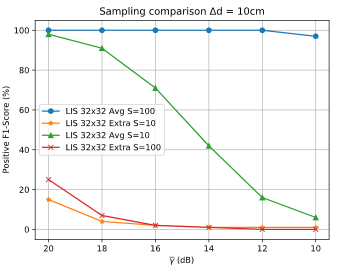
Fig. 5 shows two different ways of using the S extra samples and how they impact the robot deviation detection under different SNR conditions. The red and orange lines show that augmenting the number of samples to train the algorithm is not useful for the performance improvement. However, if we use the extra samples to average the signals (as mentioned in the previous sections), reducing the noise contribution really leads to an improvement in the results (green and blue line). The results show that S=100 is a significant amount to drastically improve the sensing performance.
Impact of antenna spacing
Along this section I will discuss the impact of the antenna spacing into the sensing performance. For this setup we will evaluate 3 different antenna spacings for a fixed aperture of 5.44 x 5.44 m LIS in a 50/10 cm parallel deviation.
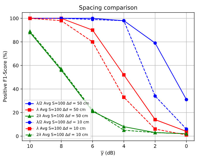
In Fig. 6 we can see the importance of a low antenna spacing under different SNR conditions. The spacing of 2λ — which is far from the concept of LIS — is presenting really inaccurate results, showing that the spatial resolution is not enough. We can conclude that the quick variations along the surface provide important information to the classifier performance. Besides, this information becomes more important the shorter the distance between the routes is. Furthermore, the effect of antenna densification for a given aperture is highlighted and it can be seen that the lowest spacing leads to the best results.
Impact of LIS aperture
Now, I will discuss the impact of the number of antennas, i.e., aperture on the sensing performance under different SNR conditions. In this section I will discuss the impact of having extra samples to train the algorithms. For this setup we will evaluate a parallel deviation of 10 cm, deploying a LIS of 32×32, 64×64 and 128×128 antennas with a spacing of half the wavelength.
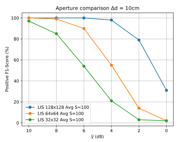
In Fig. 7 we can see the positive aspect of increasing the aperture. When increasing the number of antennas we obtain a higher resolution image leading to a better sensing performance. What is even more interesting, this shows the importance of a higher aperture and it is related to the LIS spatial consistency, i.e., the ability to obtain a continuous image.
DAE for image super resolution evaluation
In this section I will leverage the different strategies discussed along the post . For that we will deploy a 32×32 LIS and evaluate a parallel 10 cm deviation.
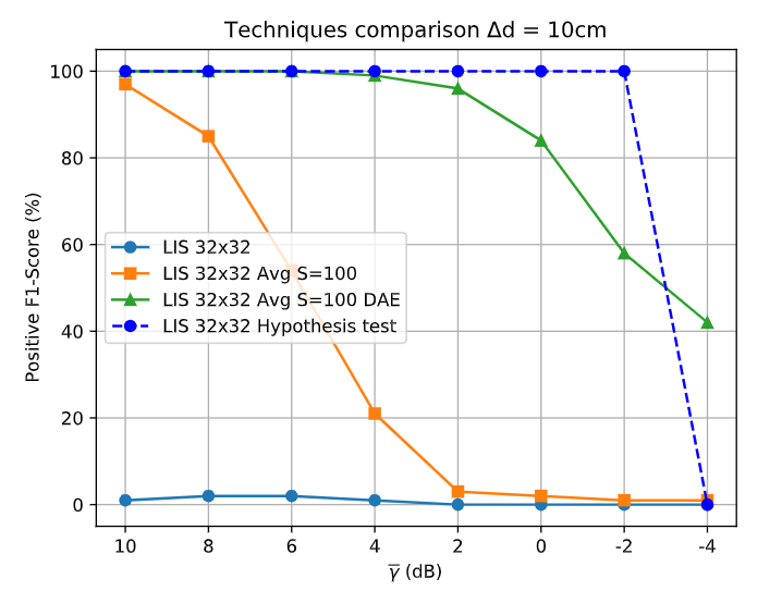
Fig. 8 shows the performance of the different methods under several SNR conditions. We can see that using only the LIS (blue line) leads to poor performance. Then, if we use the averaging strategy (orange line), we significantly improve the results. Next, by applying the Denoise Autoencoder (DAE) to augment the image resolution (green line), we see that its improvement is quite notable, approaching the benchmark solution of the statistical test (blue line) up to 2 dB SNR, which is quite an unfavourable condition.
Route deviations evaluation
Finally, now we will evaluate the impact of the separation of deviations and different types of routes in both radio image sensing and the statistical test. To that end, we fix the aperture to 32×32 and an antenna spacing of half the wavelength. We will be using all the improvements in the pre-processing of the images to leverage the performance of the ML system.
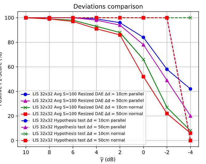
Fig. 9 shows the results for both of the trajectory deviations. We can see the system works better the closer the deviations of the routes are. This is an advantage of our proposed approach: the closer the routes are, the more accurate the reconstruction of the DAE is, taking into account the lower resolution image will be more similar to the target image, allowing a better augmentation of the image resolution. In this way, the ML proposed algorithm works better in the cases of a standard wireless sensing system which would be more prone to failure. Also, the parallel deviations are easier to detect than the normal deviations. The path loss of the points in the parallel routes remains almost identical regardless of the specific point, making it easier to detect. Also, we can see that up to 2 dB SNR the performance is quite close to the benchmark solution.
Conclusions
Along this post we have shown that Large Intelligent Surface, besides its major communication capabilities, might be of great interest for sensing tasks. We have evaluated the importance of the different parameters that characterize a Large Intelligent Surface with respect to the sensing performance. We have also shown a method and the advantage of using Large Intelligent Surface to generate images of the radio propagation environment, allowing the usage of computer vision and image processing techniques to enhance the sensing performance. We have also shown that this method leads to sensing performances in cases where standard wireless sensing method would be more prone to failure. Finally, the results obtained in this system motivate for a further study with more complex detectors of I/Q components to quantify the potential performance gain obtained from using I/Q receivers, i.e., analyzing the trade-off between the system complexity and its performance.
References
Vaca-Rubio, C. J., Ramirez-Espinosa, P., Kansanen, K., Tan, Z. H., De Carvalho, E., & Popovski, P. (2021). Assessing wireless sensing potential with large intelligent surfaces. IEEE Open Journal of the Communications Society, 2, 934-947.
Read more from Cristian >